Company Profile
ZHEJIANG BIGTORK VALVE AUTOMATION CO,.LTD was located in famous pump and valve manufacturer base--Wenzhou City, China since founded by Mr zhang in 2006. Bigtork® take part in domestic and oversea gas and oil project in 2011, and now have a extensive experience in industry valve automation and flow control. Company has signed framement agreement with SINOPEC and CNOOC as qualified Pneumatic Actuator supplier. Meanwhile, we are the reliable business partner of foreign world famous brand.
Why Choose Us?
Rich experience
BIGTORK not only focus on manufacturing Rotary & Linear and Pneumatic & Hydraulic valve actuator, but also offering one industry process control solution since founded by Mr zhang in 2006. We have 18+ extended production experience and 14+ extensive globle project undergo.
Strong R&D ability
Our team involves 6 engineers who owns domestic and oversea project work experience. We supply 100% technical support and problem solution for whole product life. Size selection tool that self owned software is avaivable for every clients.
Quality assurance
All series products strictly controlled with 9 processes by ISO and other system. The business partner of the raw material and components are profession major which supply for world renowned brand. A product warranty was provided with final testing and test report accordance with international product standards.
One stop service
Bigtork offer OEM & ODM services according to your requests from pre-sale to after-sale period. Each project has its own sale service tracking records. Each staffs is well trained to master proficient skill and full professional knowledge to support industry flow control one stop solution service.
-
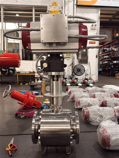
![Quarter-Turn Hydraulic Actuator]() Quarter-Turn Hydraulic ActuatorHydraulic Quarter-Turn ActuatorPowerful Drive, Precise Operation — Reliable Power for Industrial Valve Automation.This hydraulic quarter-turn pneumatic actuator is designed for industrial valve automation systems. It is suitable for valvesread more
Quarter-Turn Hydraulic ActuatorHydraulic Quarter-Turn ActuatorPowerful Drive, Precise Operation — Reliable Power for Industrial Valve Automation.This hydraulic quarter-turn pneumatic actuator is designed for industrial valve automation systems. It is suitable for valvesread more -
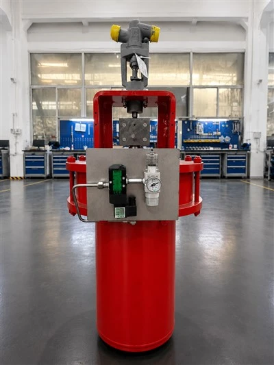
![Corrosion-Resistant Quarter-Turn Hydraulic Actuator]() Corrosion-Resistant Quarter-Turn Hydraulic ActuatorA high-performance hydraulic actuator designed for fast and reliable 90° valve control in harsh environments. Featuring 10–160 bar operating pressure, approximately 2.5-second stroke time, high torque output, and a sealed stainless-steelread more
Corrosion-Resistant Quarter-Turn Hydraulic ActuatorA high-performance hydraulic actuator designed for fast and reliable 90° valve control in harsh environments. Featuring 10–160 bar operating pressure, approximately 2.5-second stroke time, high torque output, and a sealed stainless-steelread more -
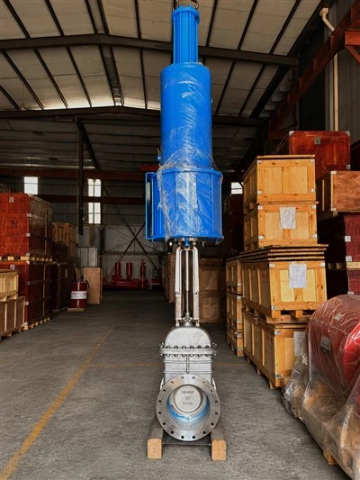
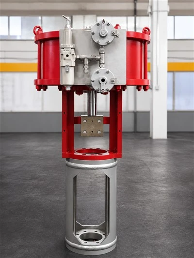
![Single Acting Hydraulic Actuator]() Single Acting Hydraulic ActuatorA single-acting hydraulic actuator is a drive mechanism in which hydraulic fluid is supplied to only one side of the piston, while a spring provides the return force on the other side. This ensures the intrinsic safety of the system inread more
Single Acting Hydraulic ActuatorA single-acting hydraulic actuator is a drive mechanism in which hydraulic fluid is supplied to only one side of the piston, while a spring provides the return force on the other side. This ensures the intrinsic safety of the system inread more -
![Butterfly Valve Hydraulic Actuator]() Butterfly Valve Hydraulic ActuatorFor a butterfly valve to start opening from a completely closed position, higher torque is required to overcome the friction between the seat and valve body. Lower torques are needed to keep the valve moving in the middle section of theread more
Butterfly Valve Hydraulic ActuatorFor a butterfly valve to start opening from a completely closed position, higher torque is required to overcome the friction between the seat and valve body. Lower torques are needed to keep the valve moving in the middle section of theread more


Hydraulic actuators are cylindrical tube and piston assemblies that utilize hydraulic power to generate linear, rotary, or oscillatory motion. This movement, in turn, is used to operate various mechanical tools and systems, such as balers, cranes, excavators, loaders, and presses. Compared to pneumatic or electrical actuators, these devices offer several advantages with regard to power, versatility, and affordability.
Benefits of Hydraulic Actuator
High torque/thrust output for operating large, heavy or high-pressure valves
Highly accurate positioning for precise process control
Fast response times to control signals, making them suitable for ESD and applications requiring fast valve actuation
Robust designs for lower maintenance requirements and longer operational life
Ability to incorporate fail-safe mechanisms in some designs, which allow the actuator to automatically return to a predetermined position in case of power loss or system malfunction
Types of Hydraulic Actuator
Linear actuator:
Linear actuators convert rotational motion into push or pull linear motion. Linear actuators are used to lift, drop, slide, or tilt many devices.
Rotary actuator:
A rotary actuator converts energy into torque through rotary motion. Rotary actuators are commonly used in industrial and manufacturing settings. It is used to control valves, gates, and other mechanical systems. All of them require linear movement.
Semi-rotary actuator:
A semi-rotary actuator is used to actuate a partial angle of motion. It can be used for partial angular movements. It can be used for a complete revolution through 360 degrees.

Application of Hydraulic Actuator
Industrial machinery: Hydraulic actuators are used in presses, injection molding machines, and CNC machines for precise movement and control of tools.
Construction equipment: They power heavy machinery like excavators, bulldozers, and cranes, allowing for lifting, digging, and material handling.
Aerospace: In aircraft, hydraulic actuators control flaps, landing gear, and other critical systems, ensuring reliable operation under varying conditions.
Automotive: Used in hydraulic brakes, power steering, and convertible roof systems, providing enhanced control and performance.
Marine applications: Hydraulic actuators are employed in steering systems, hatch covers, and anchor systems on ships and submarines.
Robotics: They enable precise movements in robotic arms and automated systems, often in manufacturing and assembly lines.
Agricultural equipment
Hydraulic systems are used in tractors and harvesters for lifting and controlling attachments like plows and seeders.
Material handling
Hydraulic actuators are used in forklifts, conveyors, and automated guided vehicles for lifting and moving materials.
Energy sector
They are used in wind turbines for blade pitch control and in oil rigs for various operational functions.
Medical devices
Hydraulic actuators can be found in hospital beds, surgical tables, and rehabilitation equipment, providing smooth and adjustable movement.
Components of Hydraulic Actuator
The main parts of hydraulic actuator are Cylinder, Piston, Spring, Hydraulic supply, Stem, Hydraulic seal, Return line
Cylinder barrel
The cylinder barrel’s seamless, thick-walled forged pipe main body requires internal machining. The cylinder barrel is sharpened or honed inside.
Cylinder base or cap
The barrel and the bottom part of most hydraulic cylinders are soldered together. If done incorrectly, this could harm the barrel’s interior.
As a result, some cylinder designs incorporate a connection between the cylinder end cap and the barrel that is threaded or flanged. This sort of barrel allows for easy disassembly and maintenance.
Cylinder head
In some cases, for simple cylinders a simple lock is used to connect the barrel and cylinder head. However, the connection is typically screwed or flanged. The best connections are flange connections, but they are expensive. Before machining, a flange needs to be weld to the pipe. The connection is fastened and always easy to remove, which is a benefit.
Piston
The piston is a small, cylindrical piece of metal that internally divides the cylinder barrel’s two halves. Usually, the piston has grooves carved into it for metal seals. These seals are frequently made of cast iron rings, U-cups, or O-rings. They stop the hydraulic oil from going by the piston and into the chamber on the other side while under pressure. The piston’s two sides have different pressures, which causes the cylinder to extend and retract. The design and material of piston seals varies depending on the pressure and temperature requirements that the cylinder will experience during operation.
In general, elastomeric seals manufactured of Viton are preferable at higher temperatures, while seals made of nitrile rubber work best in lower temperatures. Cast iron piston rings make for the greatest high temperature sealing.
Piston rod
The piston rod connects to the piston and extends from the cylinder through the rod-end head. It is normally a piece of cold-rolled steel that has been hard chrome-plated. In double rod-end cylinders, the actuator has a rod coming out of both the piston’s sides and the barrel’s ends.
The hydraulic actuator is connected to the working part of the machine by a piston rod. This connection can take the shape of a mounting accessory like a rod-clevis or rod-eye or a machine thread. These mounting attachments may be threaded, welded, or in some instances, machined into the rod-end itself to the piston rod.
Rod gland
To stop pressurized oil from seeping past the point where the rod and the head meet, the cylinder head is equipped with seals. The rod gland is the name of this region. When the extended rod retracts back into the cylinder, a rod wiper, a different seal that is frequently present, prevents impurities from entering the cylinder.
Additionally, the rod gland features a rod wear ring. The piston rod is supported by the worn ring’s function as a linear bearing to guide it as it travels back and forth through the rod gland. There are instances where the rod gland and the rod wear ring are constructed from a single integral machined element, particularly in small hydraulic cylinders.
Regular inspection: Perform routine visual inspections of the hydraulic actuator, checking for signs of leaks, corrosion, loose fittings, or damaged components. Inspect hoses, seals, and connections for wear and tear.
Fluid inspection: Monitor the condition of the hydraulic fluid. Check fluid levels, cleanliness, and temperature regularly. Contaminated or degraded fluid can lead to actuator problems.
Change hydraulic fluid: Follow the manufacturer's recommendations for changing hydraulic fluid. Contaminated or degraded fluid should be replaced promptly to maintain system performance.
Filter maintenance
Keep hydraulic filters clean or replace them as recommended by the manufacturer. Clogged filters can restrict fluid flow and lead to actuator issues.
Seal inspection
Inspect seals and gaskets for signs of wear, damage, or leakage. Replace seals that show signs of deterioration.
Lubrication
Lubricate moving parts, such as bearings and linkages, as specified by the manufacturer to prevent friction-related problems.
Tighten bolts and fittings
Regularly check and tighten bolts, fittings, and connections to prevent leaks or loosening over time.
Pressure relief
Ensure that pressure relief valves are functioning correctly to prevent overloading the actuator.
Keep external surfaces clean
Keep the exterior of the actuator clean to prevent dirt and debris from entering the system.
Hydraulic actuators work on fluid compression and convert that pressure into motion under controlled circumstances. In almost all hydraulic systems, that fluid is some form of oil. Because oil is very difficult to compress, it easily transfers large amounts of energy by volume.
Pressurized hydraulic oil is used in cylinders, which are tubes containing rams. Hydraulic actuators use pressurized fluid energy to drive the ram and operate the device or machine that the actuator serves. Pressures used in a hydraulic actuator ranges between 1,000 to 5,000 pounds per square inch (psi). Large actuators can exceed 10,000 psi for specialized applications.
Hydraulic actuators provide the greatest overall force and power density you can get with any actuator design. They’re relatively simple mechanisms with two main parts — a control device like a throttle and an actuation component such as a piston, slide or valve.

Test Methods for Various Common Tests Performed on Hydraulic Actuators
Some of these tests require a resisting force (also called a load) to be applied so the device has something to “push” or “pull” against. Such forces are often supplied by another hydraulic ram or actuator.
1.Null bias
The test for null bias measures the current supplied to the control valve required to move the actuator to the “null position”. A reference position sensor verifies that the extension length of the actuator is mechanically correct and this position is checked against the sensor built into the actuator. The reference position sensor is usually either an LVDT or encoder. The unit position sensor is almost always, in our experience, an LVDT. Note that when the control current is step-changed to move the actuation to the null bias position, the actuator position will oscillate around the null position for a while, so the position check occurs after settling.
One subtlety in this test is caused by any null region designed into the control valve. The valve spool can move back and forth a small distance in this null region without any flow occurring. The consequence is that the null position is typically specified to be within tolerance when the spool is in this null region.
2.Stroke length
The actuator should move to the expected position when commanded to do so, and this test assures that the actuator does indeed perform as expected. This test is typically done in both extend and retract directions. The position sensor is usually an LVDT or encoder or both, especially if the accuracy of the LVDT built-into the product is being compared with the measurement from a calibrated external sensor.
Furthermore, the accuracy of internal LVDT(s) is checked at a set of length extensions to check for linearity of the sensor(s). As an important but indirect check during the stroke length test, the phasing of each LVDT output is checked to verify proper wiring of the two secondary windings relative to the primary winding excitation signal. If wiring has one of the secondary outputs reversed (plus to minus) relative to the other, the output signal phase will be different by 180 degrees.
3.Velocity
This test provides a step change in position to the actuator controller and measures the time response of the actuator movement to compute the speed at which the actuator extends or retracts. This test is usually performed under both loaded and unloaded conditions.
Two flavors of this test can be performed. One type applies the maximum allowed amount of current to the unit to check the maximum velocity that the unit can produce. The second type limits the current to the unit some know amount and verifies that the unit achieves this velocity.
For loaded conditions, multiple levels of loads will be used in the test. At each pair of load and commanded velocity configurations, the unit is verified that the velocity is as expected.
4.Frequency or step response
The step response looks for the rate of change in position when commanded to perform a step positional change. A similar test commands the actuator to cycle between two positions at a set of specific frequencies to compare the command to the response. The results are used to create a Bode plot.
5.Solenoid drop-out and pull-in
The solenoid that moves the spool in the hydraulic valve requires a minimum level of current to stay in position. The drop-out test slowly reduces the supply current until the solenoid switches state (e.g., open to closed) and notes this current level compared to the specification. The pull-in test does the opposite by slowly increasing the current until the solenoid changes state and notes this current compared to the specification.
6.Hysteresis
The amount of hysteresis exhibited by the actuator is based on the hydraulic valve, solenoid, and other components in the unit. The actual hysteresis is characterized in this test whereby the actuator is moved through its range of motion forward and backwards around the null bias position. Due to the potential for non-responsive behavior around the null position, a typical hysteresis curve has a double loop for forward and reverse directions around the null position. Each one of these loops is analyzed.
7.Proof pressure
This simple but important test applies a maximum amount of hydraulic fluid pressure to the actuator components to verify that they can withstand the pressure without leaking or, worse, bursting.
8.Relief valve operation
If the hydraulic components in the actuator are subject to extreme pressure, the relief valve opens to prevent damage. This test confirms that the relief valve responds properly to over-pressure by increasing the pressure until the valve opens and comparing that pressure against the specification.
Bigtork® have covered an area of total 20000 square meters, which its workshop for machining, assemble, testing and its warehouse for raw material, semi-finished product and finished product.


Our Certificates


FAQ
As one of the leading hydraulic actuator manufacturers and suppliers in China, we warmly welcome you to buy customized hydraulic actuator at competitive price from our factory. Contact us for more details.
hydraulic actuator-
![Pneumatic Actuator WithBall Valve]() Pneumatic Actuator WithBall ValveThis is a rack-and-pinion pneumatic actuator designed for use with industrial piping systems.read more
Pneumatic Actuator WithBall ValveThis is a rack-and-pinion pneumatic actuator designed for use with industrial piping systems.read more -
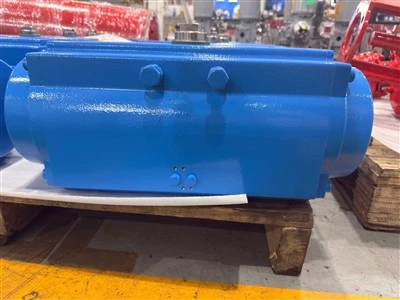
![AT190 SR Spring-returnpneumatic Actuator]() AT190 SR Spring-returnpneumatic ActuatorThe AT190SR spring-return pneumatic actuator features a robust, one-piece design with a highly recognizable blueread more
AT190 SR Spring-returnpneumatic ActuatorThe AT190SR spring-return pneumatic actuator features a robust, one-piece design with a highly recognizable blueread more -
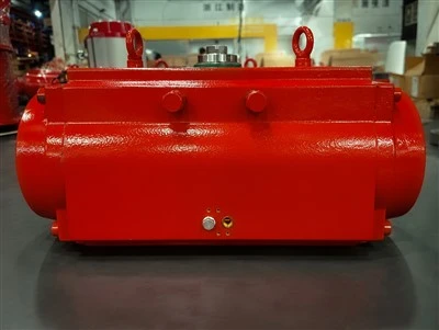
![Single-acting Rack-and-pinion Pneumatic Actuator]() Single-acting Rack-and-pinion Pneumatic ActuatorThe AT Series pneumatic actuators feature a rack-and-pinion drive mechanism and are specifically designed forread more
Single-acting Rack-and-pinion Pneumatic ActuatorThe AT Series pneumatic actuators feature a rack-and-pinion drive mechanism and are specifically designed forread more -
![FC Linear Pneumatic Actuator]() FC Linear Pneumatic ActuatorThis series of actuators consists of single-acting, linear-travel pneumatic actuators designed for the automatedread more
FC Linear Pneumatic ActuatorThis series of actuators consists of single-acting, linear-travel pneumatic actuators designed for the automatedread more -
![Double-acting Linear Actuator]() Double-acting Linear ActuatorThe BIGTORK double-acting linear actuator is designed for high-load valve control applications. Featuring aread more
Double-acting Linear ActuatorThe BIGTORK double-acting linear actuator is designed for high-load valve control applications. Featuring aread more -
![Linear Valve Actuator]() Linear Valve ActuatorThis device is specifically designed to verify the thrust performance of linear pneumatic actuators, enabling theread more
Linear Valve ActuatorThis device is specifically designed to verify the thrust performance of linear pneumatic actuators, enabling theread more